Since I was a boy I was intrigued a lot by TNC and packet Radio. In these days a TNC was a serious investment and soundcard weren”t as capable as now, plus we didn’t have (or at least I didn’t) access to programs like Direwolf and the lot. Moreover, I didn’t have access to a serious radio or receiver. Cheap SSB receivers like SDRs and XHDATA D808 were a mere dream. You would have to get a serious radio receiver with BFO and the price tag.
Now everything is simpler, and at arm reach (information and hardware). What you need is: time to fiddle with them.
My adventure with packet radio started with a very simple audio interface.§ This is more a diary for work in progress than a tutorial (there are many, and well made on the tube).
Let’s also state up front that by doing an interface like this you risk a lot damaging your valuable radio and PC. Not by chance I used an old UV3R and let my trusty Yaesu in its bag. As this is not a tutorial, I suggest you don’t follow the advice below and document yourself elsewhere very well before risking damages to your gear.
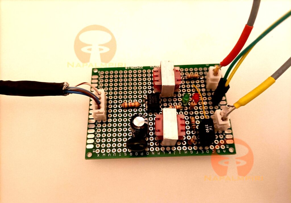
The interface is simple and it is ispired by Ivo Brugnera/I6IBE interface, but I added a total ground separation between HT and computer by using two 600 ohm transformers and a 4n25 optocoupler. The onboard led helps a lot with troubleshooting GPIO so I should definitely add it. I also added a plastic capacitor in paralle with the MIC electrolitic because I am not fond of Electrolitics. The schematic is self-explanatory, but let’s discuss a bit. Audio from HT speaker goes almost directly towards computer mic radio, with a 100 ohm resistor that I added anyway. Audio from computer goes to a couple of resistor (1k, and a trimmer partitor) and then to transformer. I could maybe dispense with electrolitic capacitor with the trasformer granting DC separation but I didn’t pay for the capacitor, so let’s put in on. This site has a circuit schematic very similar to mine (or mine is very similar to theirs)
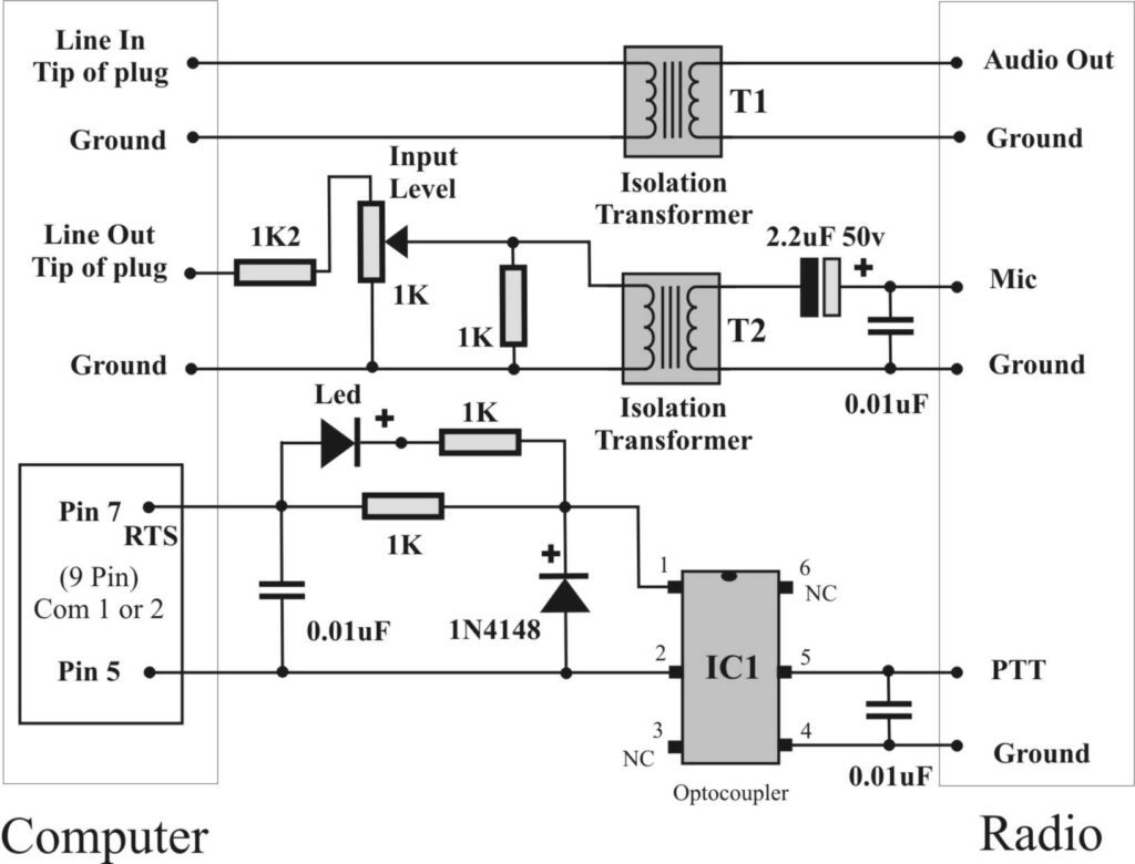
(schematic by Peter G4KQU. Photo source: https://ftp.unpad.ac.id/orari/library/library-sw-hw/amateur-radio/cw/pc-interface/PTT_to_Computer_Information.htm).
Now UV3R requires a TRRS audio jack (or 4 contacts jack) so, let’s do a little bill of components:
- 1x TRRS Jack, 3.5 mm (or two, see below. I found them online)
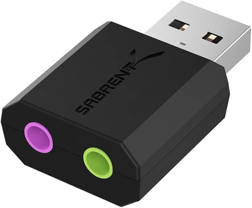
- 2x TRS jack, 3.5 mm as the soundcard has separate jack for input output.I didn’t use my other laptop with a single audio jack for stereo output and mic input, or I would obviously need another TRRS jack and YMMV. Even if they are stereo, just one contact is used (or the two channels are soldered together, I don’t recall)
- 2x 600 ohm trasformers ( few euros online).
- 1x 4N25 optocoupler
- 4x 1k Ohm resistor
- 1x 1k/4.7k Ohm trimmer (value doesn’t appear critical to me, as long as the order of magnitude is correct, and is not tool low)
- 1x 1uF-2.2uF Electrolitic capacitor,
- 10nF poly cap
- some leds (I used small ones)
- veroboard
- pcb connector (since my interface toward PC shall not vary a lot, but I have several HT I may reuse this interface by preparing a suitable HT cable with a different pinout, without resoldering cables. I found them here)
- Some shielded audio cables (mono for the interface-PC cable).
- 4 wire cable for connecting the HT to the interface. I used a shielded one.
There’s noticeble difference between I6IBE/G4KQU schematic. I don’t bring the PTT from HT directly to ground but thru a 1k Ohm value resistor (the resistor on the left of 4N25). Probably paranoid, but I didn’t pay for that resistor either, as it is reclaimed, so I bother.
Now for the computer part. I decided to use a Pine A64 board I have handy(find it here). A Rpi would be good as well and maybe better. I will connect to direwolf using a separate client by Wifi or ethernet. I am using Armbian 24.5.1 Bookworm Minimal as a distro, with minimal problems.
After downloading the distro I etched it to a suitable SD using Balena Etcher, and it booted up with no issues. I did the initial configuration with HDMI cable and keyboard and as long as WIFI was on I then switched to SSH.
$ su
# apt update && sudo apt full-upgrade -y -f
# apt install ufw
# ufw allow ssh
# ufw allow from any to any port 8000,8001 proto tcp
# apt install direwolf
the second line updates the OS. The third line installs a cute frontend for Iptables that it is handy for quick firewall configuration. As it comes with DEFAULT DENY for incoming connections I shall open the 22/TCP port for SSH and the other required ports by direwolf.
The soundcard part wasn’t hard. I used an external USB C-Media Electronics, Inc. Audio Adapter (Unitek Y-247A), very cheap (here)
now out the box aplay gives:
$ aplay -l
**** List of PLAYBACK Hardware Devices ****
card 0: sun50ia64audio [sun50i-a64-audio], device 0: 1c22c00.dai-sun8i-codec-aif1 sun8i-codec-aif1-0 [1c22c00.dai-sun8i-codec-aif1 sun8i-codec-aif1-0]
  Subdevices: 1/1
  Subdevice #0: subdevice #0
card 1: sun9ihdmi [sun9i-hdmi], device 0: SUN9I-HDMI PCM i2s-hifi-0 [SUN9I-HDMI PCM i2s-hifi-0]
  Subdevices: 1/1
  Subdevice #0: subdevice #0
card 2: Device [USB Audio Device], device 0: USB Audio [USB Audio]
  Subdevices: 1/1
  Subdevice #0: subdevice #0
So my direwolf.conf gives:
#Removing the # will enable the setting

#Device Audio Settings
ADEVICE plughw:2,0
ACHANNELS 1
CHANNEL 0
Does this persist during reboots? NO. TODO: find a way to persist the soundcard number.
The trimmer on the interface was placed roughly in the middle, and everything seems to work fine.
On the Baofeng UV3R sides, frequency is 144.800 (APRS frequency for Italy region) and setting were pretty simple:
- Squelch Disabled (0)
- VOX OFF (we don’t need, we will trigger PTT using A64 GPIO)
- BCLO OFF (we don’t need channel protection here). Since squelch is off, the radio will hear the freq as busy. if BCLO is on, the transceiver won’t transmit. One could maybe leave SQL a 1 and BCLO on, I have to try
Now for the ‘hardest part’ or the GPIO configuration for A64. I could use a FTDI Usb interface (I have tested with a PC, it works) but there’s two order of problems. First, the DTS and RTS outputs on the USB FTDI will stay HIGH until direwolf is launched or if direwolf crashed. This means that the HT will transmit while the outputs are HIGH. There are ways around this on Windows, but I highly prefer something more robust.
I did some test with a resistor and a led in series. When this worked, I was ready to test with the interface. As LED are polarized, if test fails it may useful to try and invert pins.
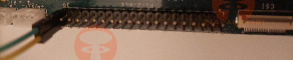
I simply followed this thread and use pins 39-40 from the Pi2 header of the A64. A more elaborate howto is here. Pin assignment is here (a local copy below, courtesy and credits to pine64.org. Local copy may be outdated)
I didn’t copy the values from the sheet to direwolf configuration, there’s some math involved, I cite
To convert a hardware port name (PXn) to a Linux port number, use the formula:

32 * X + n
where "X" is the letter's ASCII value minus 65 (so A = 0, B = 1, C = 2, ...) and "n" is the following decadic integer. For example, PG7 is 32*6 + 7 = 199.
so in my case, pin 40 on the PI2 Bus is PC11, C is 2, so 32*2+11=75
# setup
echo "75" > /sys/class/gpio/export
echo "out" > /sys/class/gpio/gpio75/direction

# other interesting bits
# to test the led or the PTT without direwolf
echo 1 > /sys/class/gpio/gpio75/value #led on
echo 0 > /sys/class/gpio/gpio75/value #led off

# to unexport the GPIO, shall I decide I don't want to use it anymore)
# echo "75" > /sys/class/gpio/unexport
and 75 is the value of the GPIO I will write in the relevant direwolf.conf. Will this persist after reboot? The world wonders. NO. Besides /sys/class/gpio is deprecated. Read more about this here.
#Removing the # will enable the setting

#Device Audio Settings
ADEVICE plughw:2,0
ACHANNELS 1
CHANNEL 0

#Your Station Call
MYCALL MYHAMCALL

#Packet Speed 1200 Baud
MODEM 1200

#PTT Method (USB OR GPIO / LED Can Be Used Simultaneously)
#PTT /dev/ttyUSB0 RTS DTR
PTT GPIO 75
Now this is still far from true headless operation. Sound card number will vary, and I have to modify it in direwolf.conf. GPIO export will not persist, and I will have to redo it by hand. Beside all this, direwolf can’t access GPIO when run as normal user and asks for sudo (e.g it is running as root, and that is less than optimal. The soundcard issue seems to be manageble:
# cat /proc/asound/card*/id
Device
sun50ia64audio
sun9ihdmi
Then, in /etc/modprobe.d I create a soundcards.conf file and modify direwolf.conf to use the device 0:
# Set this to the correct number of cards.
options snd cards_limit=3

options USB id=Device index=0
options sun9i-hdmi  id=sun9ihdmi index=1
options ssun50i-a64-audio id=sun50ia64audio index=2
The issue for the GPIO export persistance is similarly approached by creating a /usr/local/bin/gpiopersist file and making it executable:
#!/bin/sh
start() {
echo "75" > /sys/class/gpio/export
echo "out" > /sys/class/gpio/gpio75/direction
}

stop() {
echo "75" > /sys/class/gpio/unexport
}

case $1 in
  start|stop) "$1" ;;
esac
and by creating a systemd service, something like /etc/systemd/system/gpiopersist.service file
[Unit]
Description= Persist gpio setting for direwolf

[Service]
Type=oneshot

[Install]
WantedBy=multi-user.target
[Service]
Type=oneshot
ExecStart=/usr/local/bin/gpiopersist start
ExecStop=/usr/local/bin/gpiopersist stop
RemainAfterExit=yes

[Install]
WantedBy=multi-user.target
and then by enabling it:
# systemctl enable --now gpiopersist.service
The GPIO permission issue shall be similar to take, but this something for tomorrow.
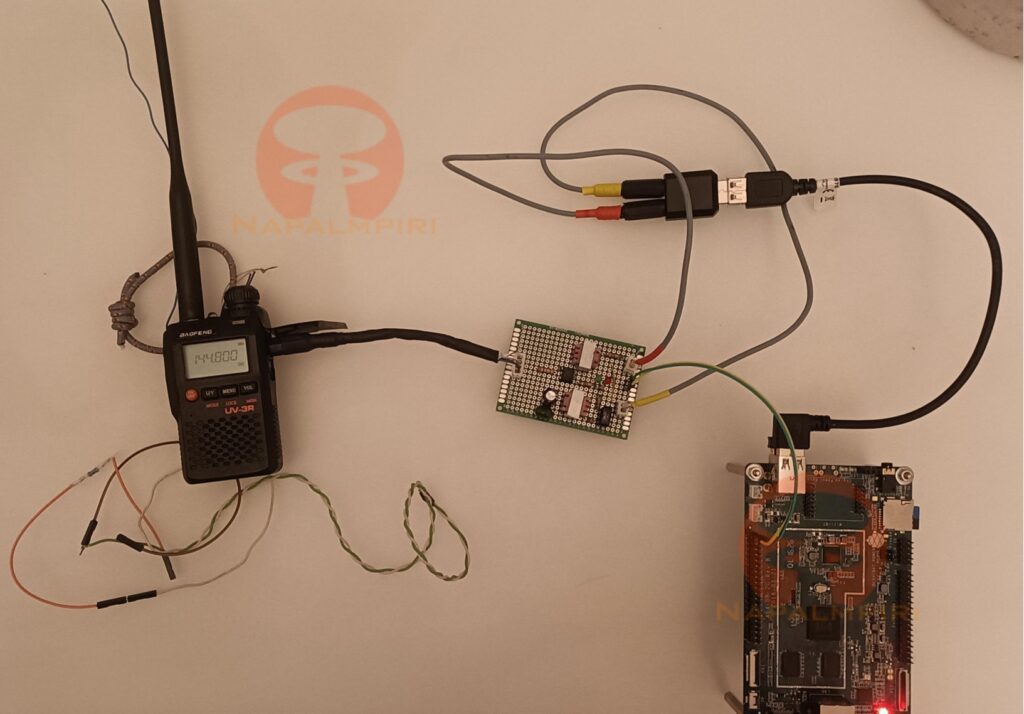
The finished rig. The wires in the left angle are the test led. The wire from the HT antenna is a counterpoise.